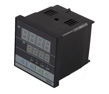
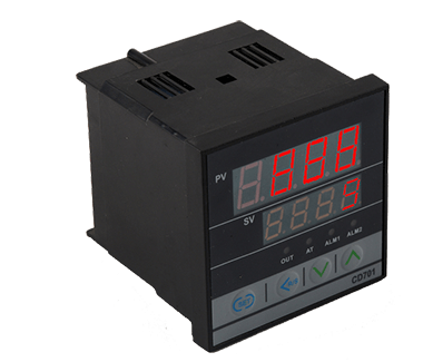
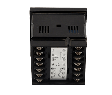
CD701 temperature controller

Data sheet

Product Details

CD/CH Series CD701


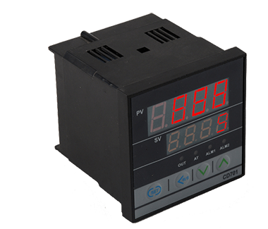
This series instruments are intelligent double-row four-digit display instruments, which display measured values and set values respectively. They can input a variety of signals. The instrument is equipped with four-button operation, easy parameter setting and convenient input of information. The control method have two-position control and PID control. The instrument adopts super anti-interference chip design and the quality is reliable.


The control modes have PID control and position control (also known as the hysteresis control or the upper and lower limit control). The PID control is a professional control method suitable for industrial control situations requiring high precision measurement control. PID is the abbreviation for proportion, integral, and differential. PID control combined the advantages of the three and have the function of timely and rapid proportion action, the ability to eliminate residuals with integral action, and the advanced control function of differential action. In addition, the self-tuning function of the meter can automatically calculate the optimal P.I.D. parameter value according to the control effect of the controlled object and automatically save it.
This series instruments are also with high cost performance.


Heating/Cooling control
Digital communication

Heating/Cooling control

Auto adjusting function

Digital communication

Big screen LED display

Industrial tandard microcomputer processor
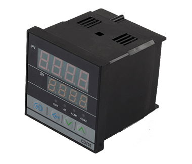
1.Outline dimension

See the outline dimension picture


2.Control Mode

F:PID operation and auto calculating   (reverse operation)

D:PID operation and auto   calculating(Forward operation)

W:eating/cooling PID operation and auto   calculating(cooling water)*1

A:heating/cooling PID operation and auto   calculating(cooling water)*1

3.Input mode

Refer to Input Range Table


4.Range Code

Refer to Input Range Table


5.First control
  output(OUT1)
  (Heating side)

M: Relay contact output
  V: Voltage impulse output
  T: Thyratron output

8: Current output(IC4-20mA)
  G: Thyratron driving & triggering output

6.Second control
  output( OUT2)
  (Cooling side)*2

No mark: when the control mode is F or D
  M: Relay contact output
  V: Voltage impulse output

T: Thyratron output
  8: Current output(IC 4-20mA)

7.First alarm(ALM1)
  8.Second alarm (ALM2)*2

N: no alarm
  A: Upper-limit bias alarm
  B: Lower-limit bias alarm
  C: Upper/lower limit bias alarm
  D: alarm in area
  E: Standby upper-limit bias alarm attached
  F: Standby lower-limit bias alarm attached
  G: Standby upper/lower limit bias alarm
  H: Upper-limit input value alarm

J: lower-limit input alarm
  K: Standby upper-limit input alarm attached
  L: Standby lower-limit input alarm attached
  P: Heater breakage alarm(CTL-6)*3
  S: Heater breakage alarm(CTL-12)*3
  R: Control line breakage alarm *4
  V: Upper-limit set value alarm
  W: Lower-limit set value alarm

9.Communication*5

N:No communication

5:RS-485(two-wire system)

10.Water-proof/dust-proof

N:no water-proof/dust-proof

1:with water-proof/dust-proof


Refer to Input Range   Table


Input type

Set range

Input type

Set range

Thermocouple Input(TC)

K

0 to 1372°C(0 to 2502 F)

J

0 to 1200°C(0 to 2192 F)

R

0 to 1769°C(0 to 3216 F)

S

0 to 1769°C(0 to 3216 F)

B

0 to 1820°C(0 to 3308 F)

E

0 to 1000°C(0 to 1832 F)

N

0 to 1300°C(0 to 2372 F)

T

-199.9 to +400.0°C(-199.9 to +752.0 F)

W5Re/W26Re

0 to 2320°C(0 to 4208 F)

PL

0 to 1390°C(0 to 2534 F)

L

0 to 900°C(0 to 1652 F)

U

-199.9 to +600.0°C(-199.9 to +999.9 F)

RTD Input Pt

100Ω(JIS/IEC)

-199.9 to +649.0°C
  (-199.9 to +999.9 F)

JPt100Ω(JIS)

-199.9 to +649.0°C
  (-199.9 to +999.9 F)

Voltage input

0 to 5V DC

1 to 5V DC

-1999 to +9999(programmable range)

Current input

0 to 20mADC

4 to 20mADC

-1999 to +9999(programmable range0)


CD701 temperature controller

CD/CH Series CD701


This series instruments are intelligent double-row four-digit display instruments, which display measured values and set values respectively. They can input a variety of signals. The instrument is equipped with four-button operation, easy parameter setting and convenient input of information. The control method have two-position control and PID control. The instrument adopts super anti-interference chip design and the quality is reliable.


The control modes have PID control and position control (also known as the hysteresis control or the upper and lower limit control). The PID control is a professional control method suitable for industrial control situations requiring high precision measurement control. PID is the abbreviation for proportion, integral, and differential. PID control combined the advantages of the three and have the function of timely and rapid proportion action, the ability to eliminate residuals with integral action, and the advanced control function of differential action. In addition, the self-tuning function of the meter can automatically calculate the optimal P.I.D. parameter value according to the control effect of the controlled object and automatically save it.
This series instruments are also with high cost performance.


Heating/Cooling control
Digital communication

Heating/Cooling control

Auto adjusting function

Digital communication

Big screen LED display

Industrial tandard microcomputer processor
1.Outline dimension

See the outline dimension picture


2.Control Mode

F:PID operation and auto calculating   (reverse operation)

D:PID operation and auto   calculating(Forward operation)

W:eating/cooling PID operation and auto   calculating(cooling water)*1

A:heating/cooling PID operation and auto   calculating(cooling water)*1

3.Input mode

Refer to Input Range Table


4.Range Code

Refer to Input Range Table


5.First control
  output(OUT1)
  (Heating side)

M: Relay contact output
  V: Voltage impulse output
  T: Thyratron output

8: Current output(IC4-20mA)
  G: Thyratron driving & triggering output

6.Second control
  output( OUT2)
  (Cooling side)*2

No mark: when the control mode is F or D
  M: Relay contact output
  V: Voltage impulse output

T: Thyratron output
  8: Current output(IC 4-20mA)

7.First alarm(ALM1)
  8.Second alarm (ALM2)*2

N: no alarm
  A: Upper-limit bias alarm
  B: Lower-limit bias alarm
  C: Upper/lower limit bias alarm
  D: alarm in area
  E: Standby upper-limit bias alarm attached
  F: Standby lower-limit bias alarm attached
  G: Standby upper/lower limit bias alarm
  H: Upper-limit input value alarm

J: lower-limit input alarm
  K: Standby upper-limit input alarm attached
  L: Standby lower-limit input alarm attached
  P: Heater breakage alarm(CTL-6)*3
  S: Heater breakage alarm(CTL-12)*3
  R: Control line breakage alarm *4
  V: Upper-limit set value alarm
  W: Lower-limit set value alarm

9.Communication*5

N:No communication

5:RS-485(two-wire system)

10.Water-proof/dust-proof

N:no water-proof/dust-proof

1:with water-proof/dust-proof


Refer to Input Range   Table


Input type

Set range

Input type

Set range

Thermocouple Input(TC)

K

0 to 1372°C(0 to 2502 F)

J

0 to 1200°C(0 to 2192 F)

R

0 to 1769°C(0 to 3216 F)

S

0 to 1769°C(0 to 3216 F)

B

0 to 1820°C(0 to 3308 F)

E

0 to 1000°C(0 to 1832 F)

N

0 to 1300°C(0 to 2372 F)

T

-199.9 to +400.0°C(-199.9 to +752.0 F)

W5Re/W26Re

0 to 2320°C(0 to 4208 F)

PL

0 to 1390°C(0 to 2534 F)

L

0 to 900°C(0 to 1652 F)

U

-199.9 to +600.0°C(-199.9 to +999.9 F)

RTD Input Pt

100Ω(JIS/IEC)

-199.9 to +649.0°C
  (-199.9 to +999.9 F)

JPt100Ω(JIS)

-199.9 to +649.0°C
  (-199.9 to +999.9 F)

Voltage input

0 to 5V DC

1 to 5V DC

-1999 to +9999(programmable range)

Current input

0 to 20mADC

4 to 20mADC

-1999 to +9999(programmable range0)